Sunday, April 17, 2016
Hotrodding a Holiday Light Controller
So last week we had a look at the neon bulbs in the Electric Votary. The effect of lighting individual electrodes is accomplished by driving them with DC in both polarities. Here I describe the circuit to do that, based on an inexpensive holiday light controller.
I built this back in the late '90s when LED holiday lights were much less widespread: most decorative lights used incandescent bulbs. To drive these in changing patterns, inexpensive controllers using SCRs were common. (If you need a refresh on how SCRs work, here's the relevant wikipedia page.) I hacked many of these controllers as they were cheap and provided four channels of sequencing as well as dimming using phase control of the SCRs. Typically these were so cheap they had off-brand controller ICs or COB glob-tops, though I did manage to find a (sadly no longer) commercially available controller IC: the Holtek 2040A. Here's the application circuit from the Holtek 2040A data sheet (pdf link):
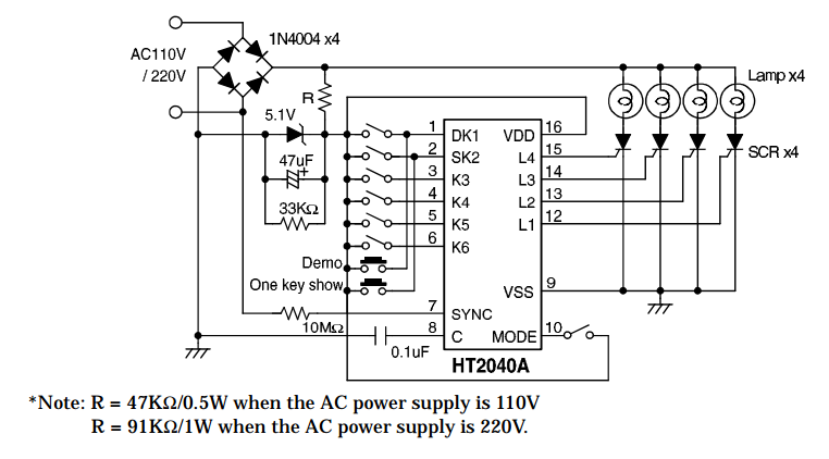
This circuit is a small triumph of cheap-ass engineering. The 5VDC power VSS comes from a voltage divider off the rectified mains, clamped with a zener. Since this is likely a CMOS chip consuming a few mA at most, this is a fine solution without the complexity and cost of a proper switching converter. The 10M resistor from the AC mains is used to determine the line phase for phase-control dimming. Sadly this chip seems no longer available, but a microcontroller could drive the SCRs just as well with a little bit of programming and a way to determine line phase. Here's a STM application note about doing that.
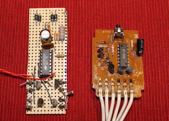
On the right in the image below is a commercial controller, with a house-marked DIP: note the manufacturers were so cheap they only stuffed three of the four output channels! My hacked version is on the left, the red wires go to a mode selection switch.
On to the hack. A neon bulb connected to the stock Holtek controller circuit above will light with the appropriate pattern, but only one electrode will turn on as the voltage across it is DC. However, with the addition of a few diodes, I was able to make bipolar voltages needed to light both electrodes individually. Here's the circuit I used:
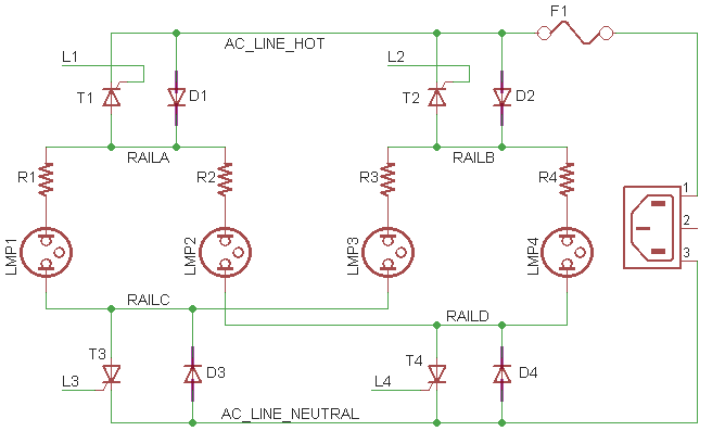
I had forgotten details about this modification other than I threw in a couple of diodes but on reinspection it's kind of wonderfully bonkers. It's quite similar to the stock Holtek circuit above but with the addition of four diodes D1-D4 (I used pretty standard 1N4004 variety). L1-L4 are the SCR drive signals from the controller IC, and R1-R4 are the current limiting resistors for the neon bulbs (about 33K for NE-2s).
In practice the circuit works not unlike an H-bridge. Imagine the SCR T1 turned on in forward conduction mode; it will pass current when forward biased during the negative AC phase. Thus there would be a current path from the AC neutral, through D3 to RAILC, and through LMP1 (turning on the lower electrode) and R1, and T1. When the line phase goes positive, T1 will turn off in reverse blocking mode. The other three channels work similarly, allowing 16 different combinations of lamp electrodes to be turned on or off. (Exercise for the reader: what combinations of lit/unlit electrodes are not achievable with this circuit?)
Next week if I get around to it I will post video of other neon pieces built using this hack. A Nixie tube is especially interesting because you're not supposed to drive them backwards! :)
I should add the typical disclaimer about lethal voltages blah blah blah: if you experiment with this kind of circuit you will definitely want to know what you are doing, and I'm certainly not responsible if you don't. Have fun!